FRANCIS TURBINE - HOW IT WORKS
What are Francis Turbine?

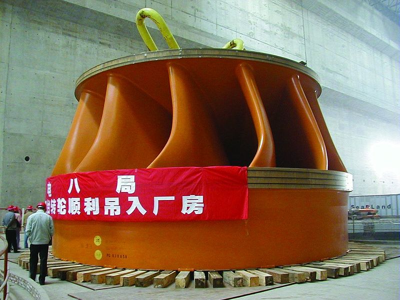
The Francis turbine is an inward flow reaction turbine which was designed and developed by the American engineer James B. Francis. Francis turbine has a purely radial flow runner; the flow passing through the runner had velocity component only in a plane of the normal to the axis of the runner.

Reaction hydraulic turbines of relatively medium speed with radial flow of water in the component of turbine are runner.
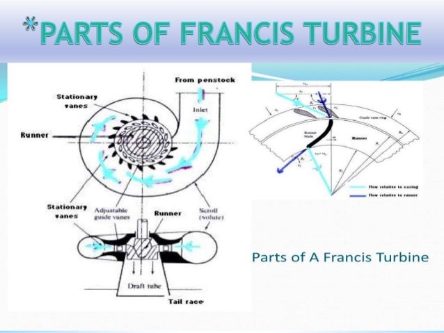
Components of the Francis turbine:-
· Pen stoke: – It is a large sized shaped; where the water is provided to the turbine runner from the dam.
· Scroll casing: – Penstocks connected to and feeds water directly into an annular channel surrounding the turbine runner. The channel is spiral in its layout.
· Guide vanes: – A series of airfoil shaped vanes called the guide vanes are arranged inside the casing to form a number of flow passages between the casing and the runner blades. Guide vanes are fixed in position (they do not rotate with rotating runner).
· Guide wheel and governing mechanism: – It changes the position of guide blades to affect variation in the water flow rate in the wake of changing load conditions on the turbine. When the load changes, the governing mechanism rotates all the guide blades about their axis through the same angle so that the water flow rate to the runner.
· Runner and runner blades: – Runner of the Francis turbine is a rotor which has passages formed between the drat tube and scroll casing.
· Draft tube: – After passing through the runner, the water is discharged to the tail race through a gradually expanding tube.
WORKING OF FRANCIS TURBINE: The amount of water falls on the vanes (buckets) of the runner. The turbine rotor is called runner. Runner revolves at constant with the help of governing mechanism.
The runner shaft is connected with the generator; thus the electricity is produce with the help of generator. And the water is discharge from the tail race.
THEORY OF OPERATION: The Francis turbine is a reaction turbine, which means that the working fluid changes pressure as it moves through the turbine, giving up its energy. A casement is needed to contain the water flow. The turbine is located between the high pressure water source and the low pressure water exit, usually at the base of a dam.
The inlet is spiral shaped. Guide vanes direct the water tangentially to the runner. This radial flow acts on the runner vanes, causing the runner to spin. The guide vanes (or wicket gate) may be adjustable to allow efficient turbine operation for a range of water flow conditions.
As the water moves through the runner its spinning radius decreases, further acting on the runner. Imagine swinging a ball on a string around in a circle. If the string is pulled short, the ball spins faster. This property, in addition to the water’s pressure, helps inward flow turbines harness water energy.
At the exit, water acts on cup shaped runner features, leaving with no swirl and very little kinetic or potential energy. The turbine’s exit tube is specially shaped to help decelerate the water flow and recover kinetic energy.

APPLICATION: Francis Inlet Scroll, Grand Coulee Dam Large Francis turbines are individually designed for each site to operate at the highest possible efficiency, typically over 90%. They are best suited for sites with high flows and low to medium head. Francis Turbines are very expensive to design, manufacture and install, but operate for decades.
In addition to electrical production, they may also be used for pumped storage; where a reservoir is filled by the turbine (acting as a pump) during low power demand, and then reversed and used to generate power during peak demand.

Francis turbines may be designed for a wide range of heads and flows. This, along with their high efficiency, has made them the most widely used turbine in the world.
No comments:
Post a Comment